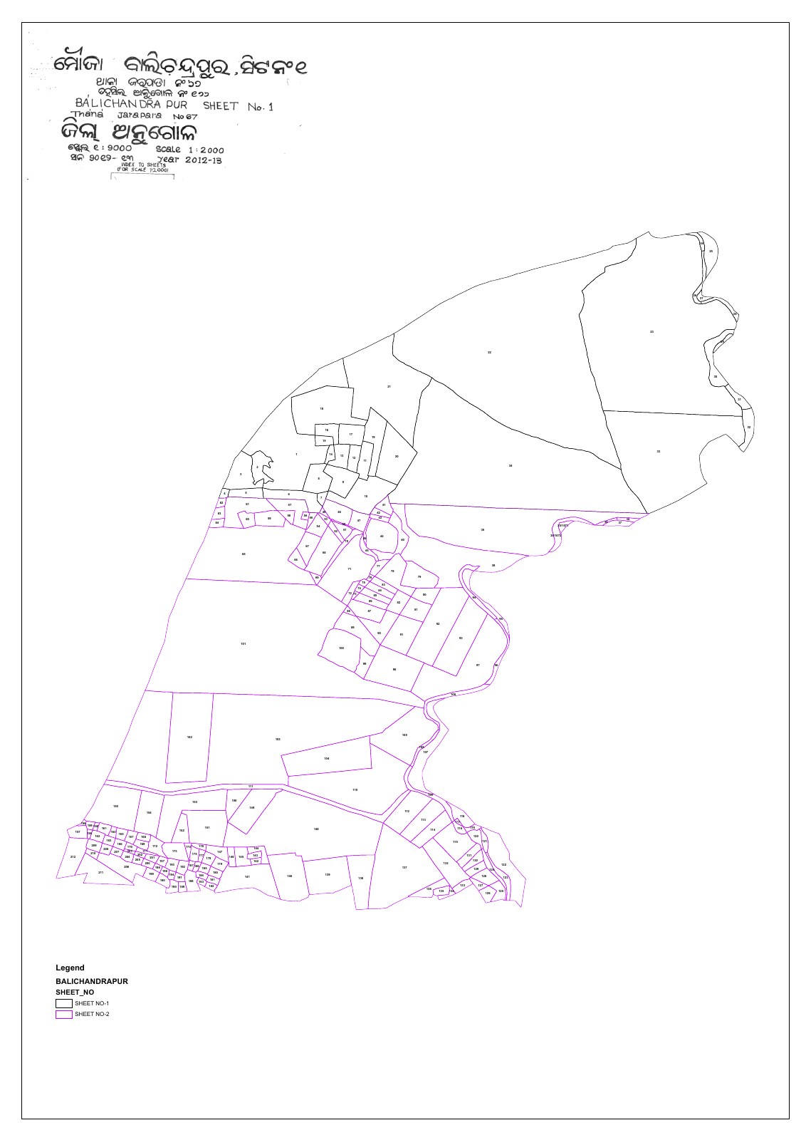
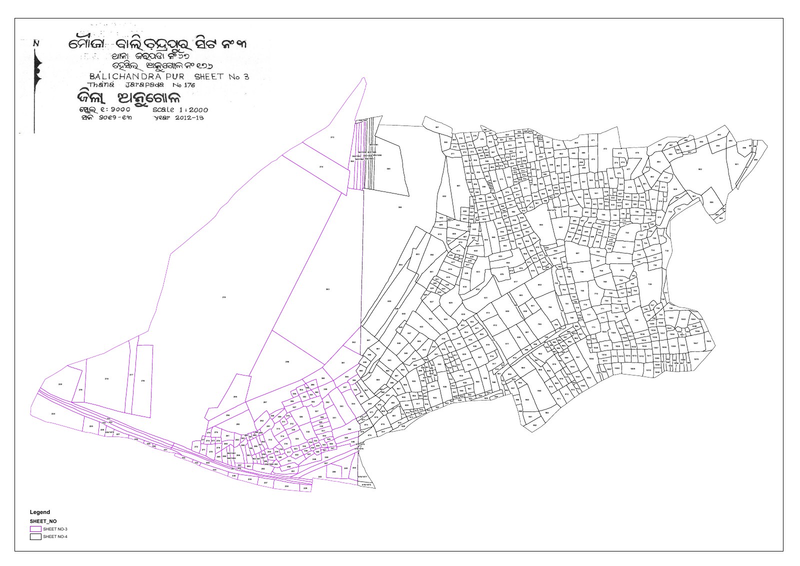
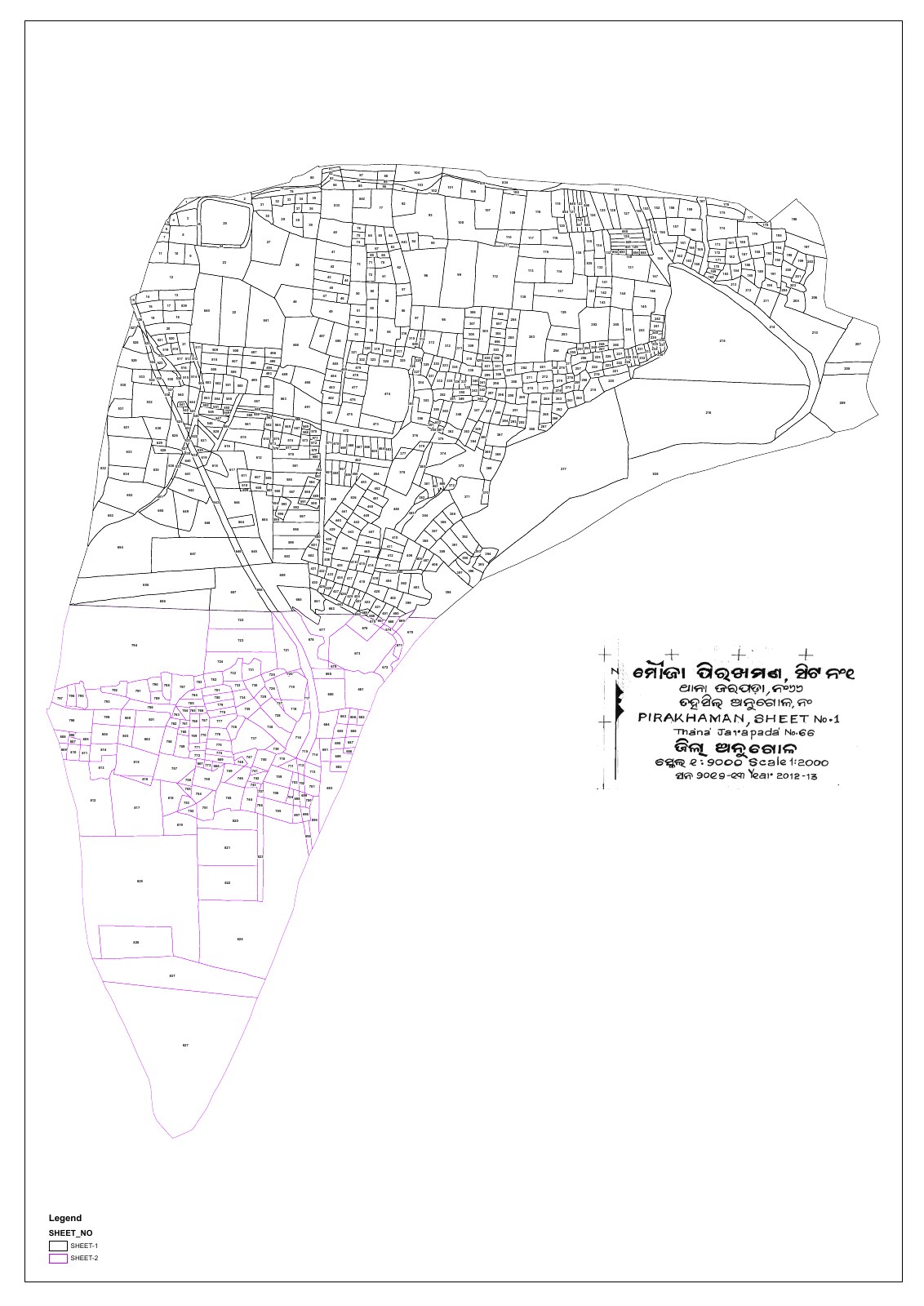
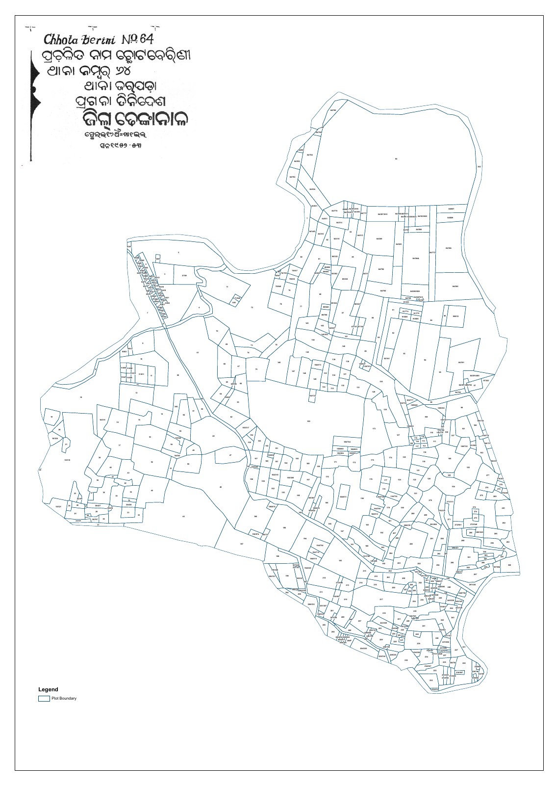
Main drainage-survey requirements
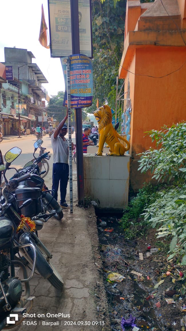
- Measurement of the length and depth of the internal cross-section of drains at every section point and at additional required points
- Recording the existing physical condition of drains
- Measurement of silt or other deposits, wherever present
- Measurement of the water level inside drains
- Identification of high-flood levels through consultation with the local body
- Identification and recording of existing drain outfall points
Project objective
The basic objective was to determine the three-dimensional positions of ground features as X, Y and Z coordinates with respect to a defined reference system. The survey data was intended to generate an accurate digital terrain model, prepare contour plans, support engineering design, identify required improvements and facilitate planning of additional drainage facilities.
Scope of work
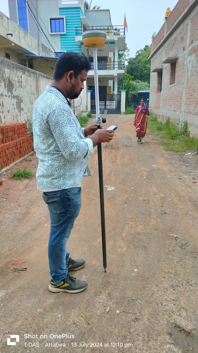
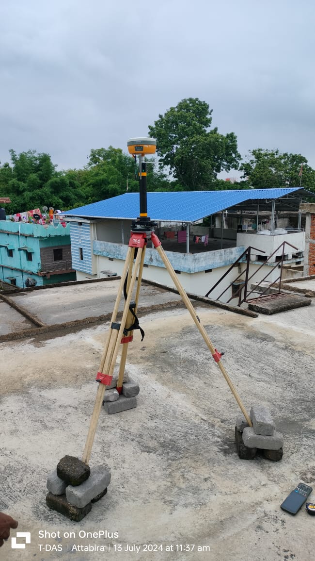
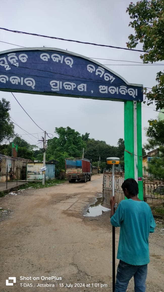
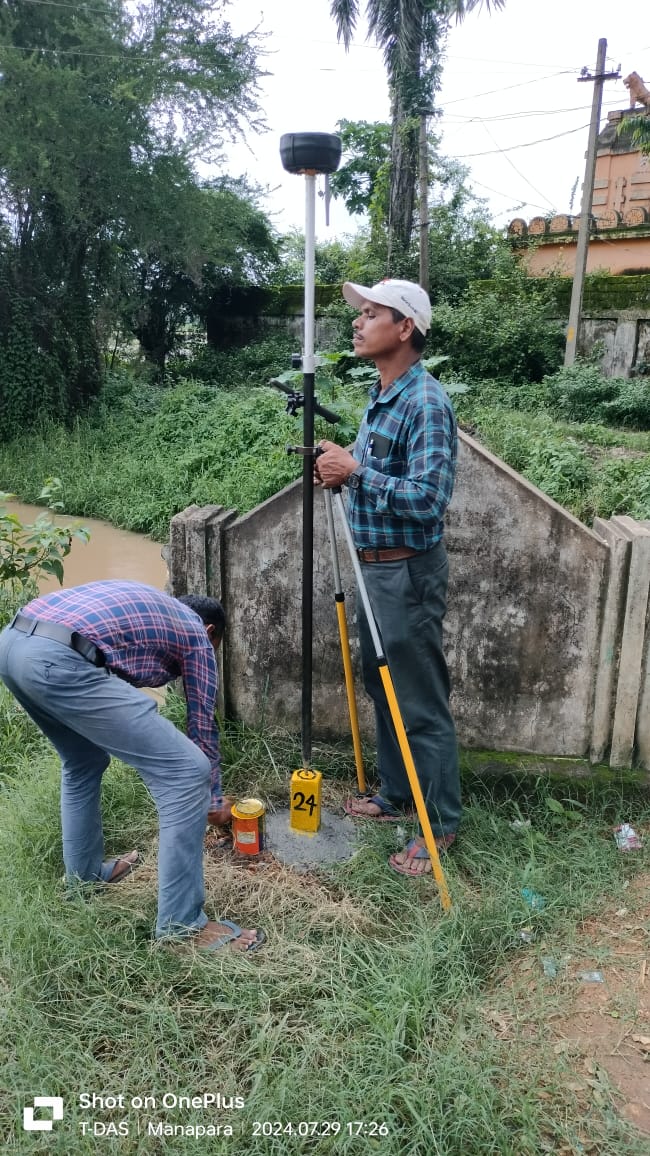
- Identification and demarcation of boundary-reference points using Differential Global Positioning System (DGPS)
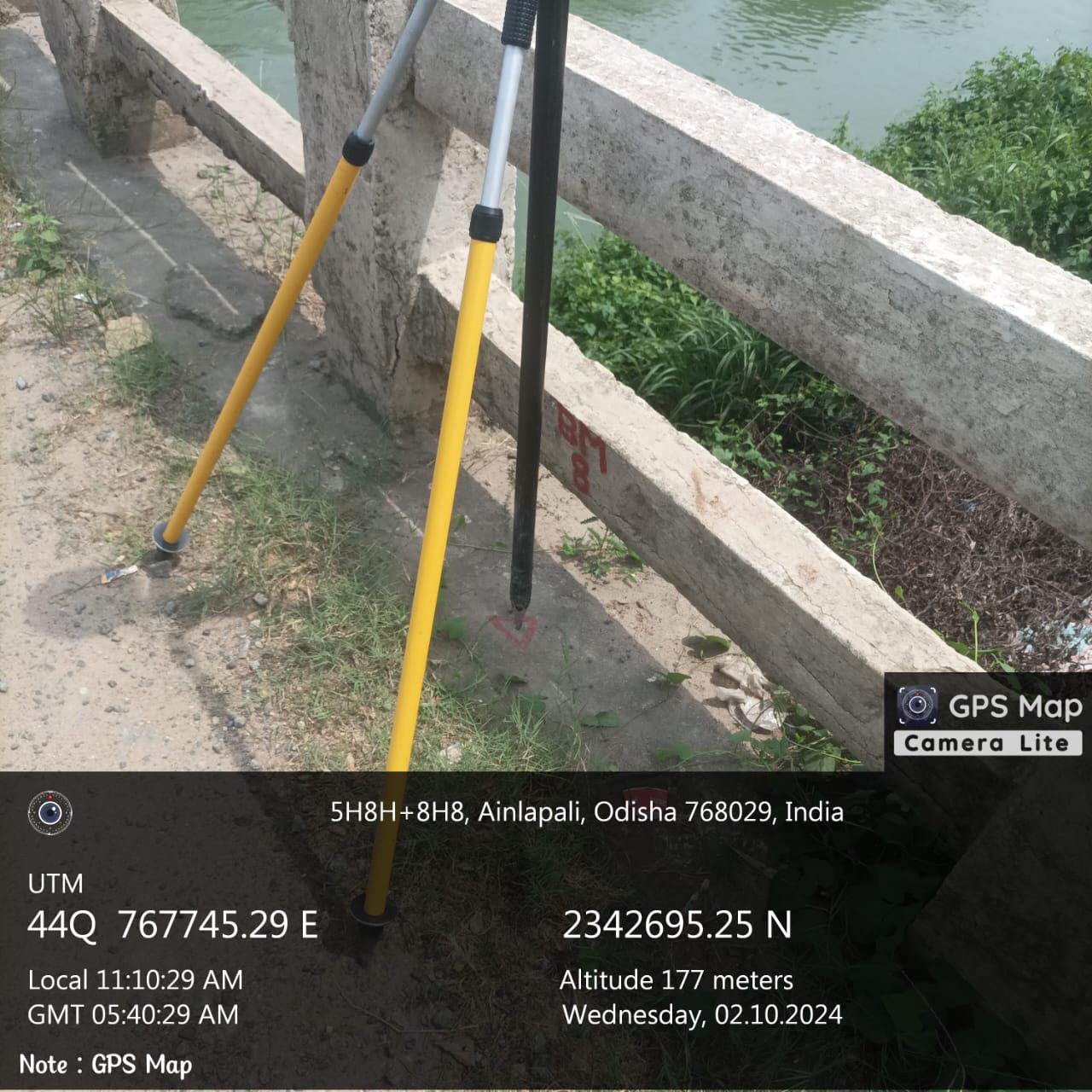
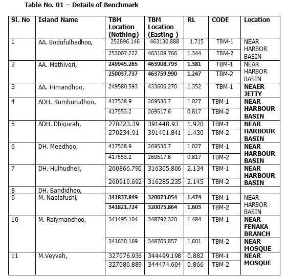
- Transfer of the Temporary Bench Mark value from the ORSAC reference point at Godabhanga School to the project site
- Conversion of the complete project area into a 50 m × 50 m grid system
- Collection of longitude, latitude and altitude values for grid points
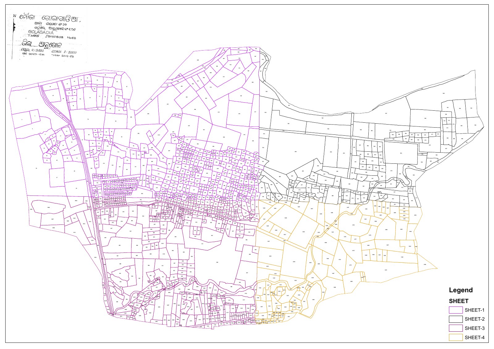
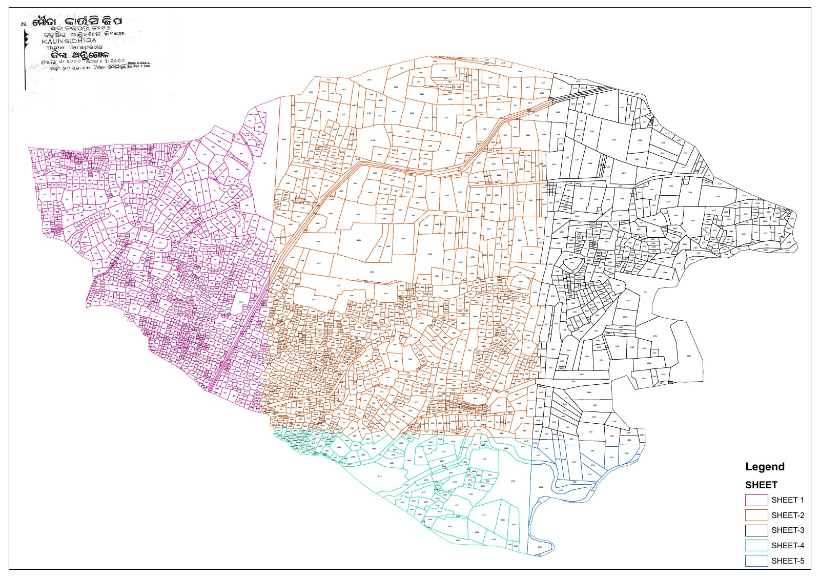
- Preparation of contour maps for the project area
Terrain and survey-control methodology
The project site is situated on generally plain terrain, with elevations varying from approximately 180 m to 205 m. The reduced level of 175.266 m was transferred from the ORSAC point at Godabhanga School to the project site by traversing with a dual-frequency DGPS instrument within permissible error limits.
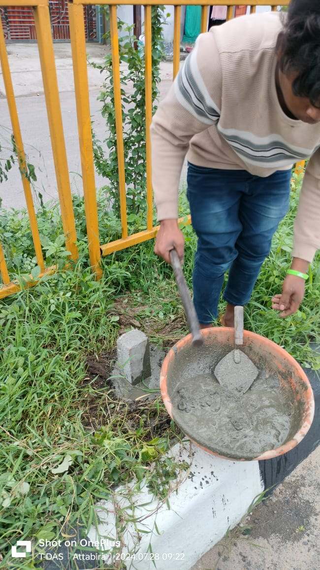
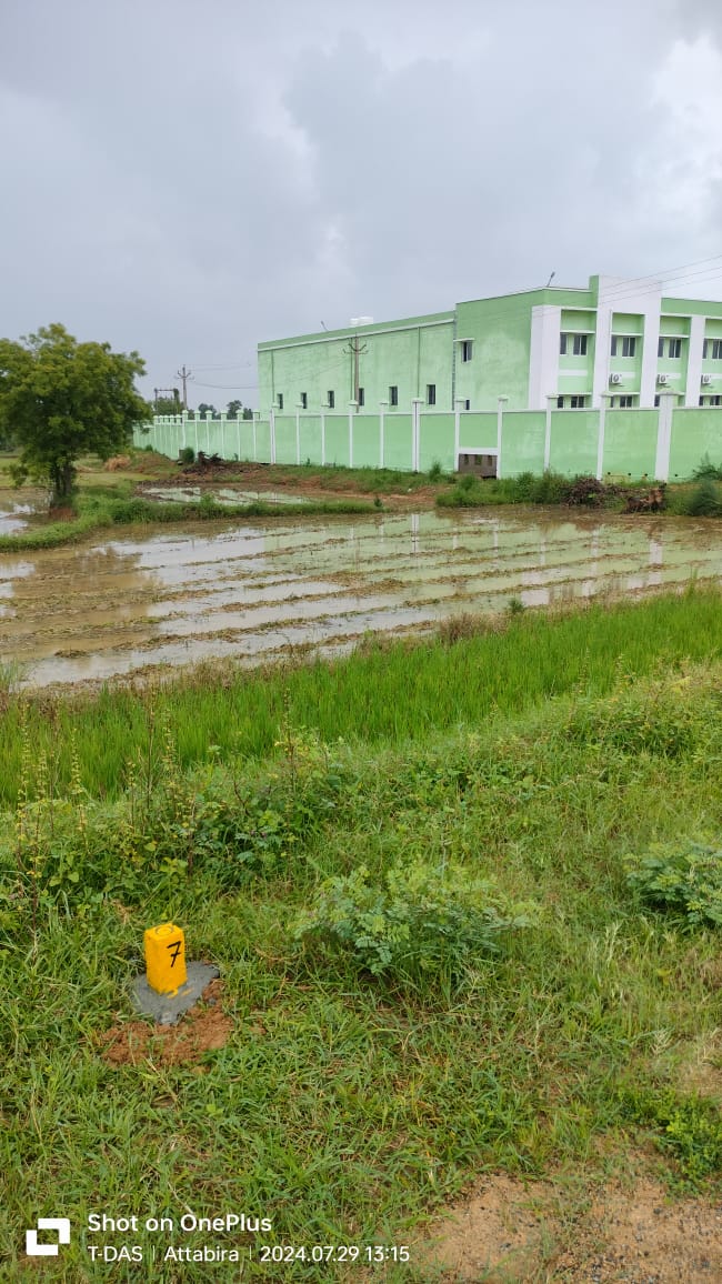
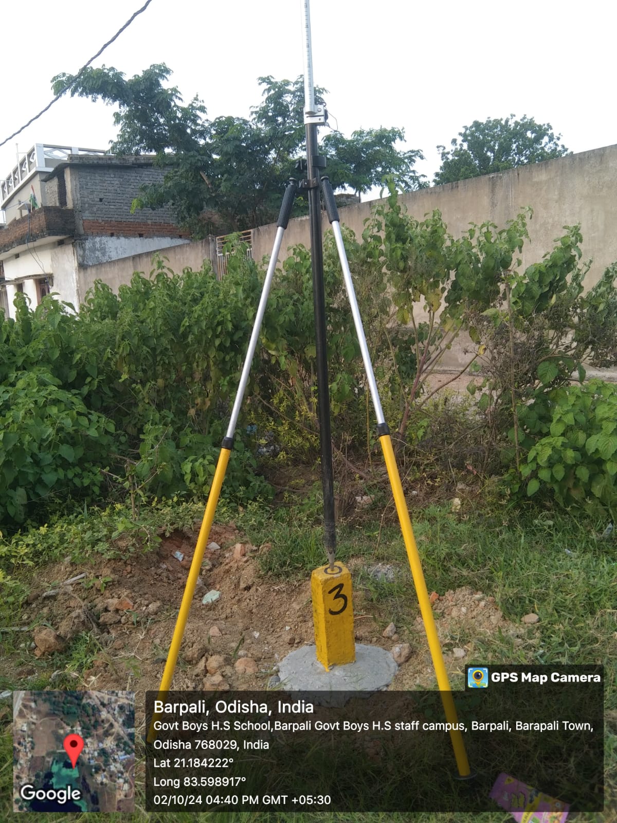
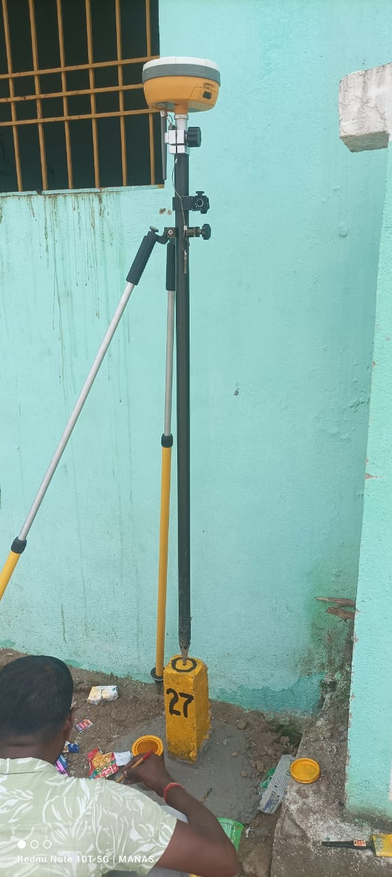
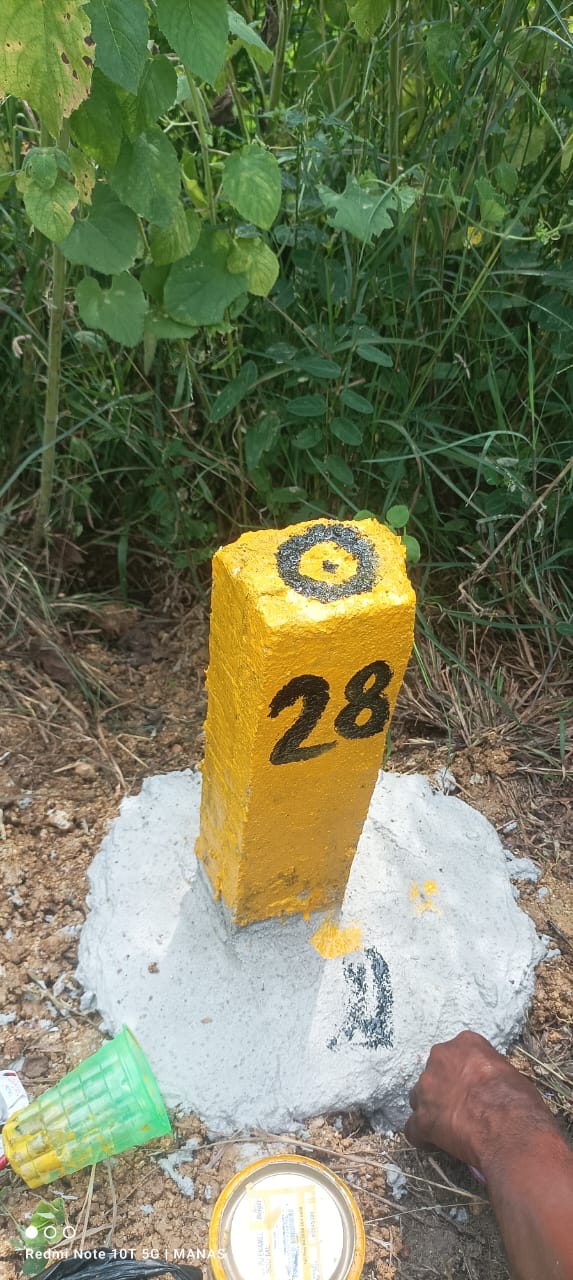
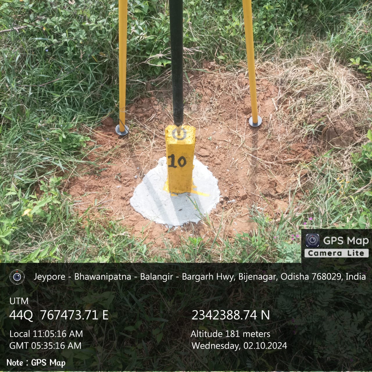
Main survey control was established through RCC ground-control pillars measuring approximately 100 mm × 100 mm and 750 mm in height, with an iron pin fixed at the top centre. The pillars were embedded securely, painted and uniquely numbered.
DGPS observations and detailed topographical survey
Trimble multi-frequency GNSS receiver instruments were used for control establishment. DGPS observations were taken continuously for approximately eight hours at the project Temporary Bench Mark. Coordinates were computed using single-point positioning and baseline modes, and latitude and longitude values were projected to X and Y grid coordinates using the Universal Transverse Mercator projection, Zone Q44.
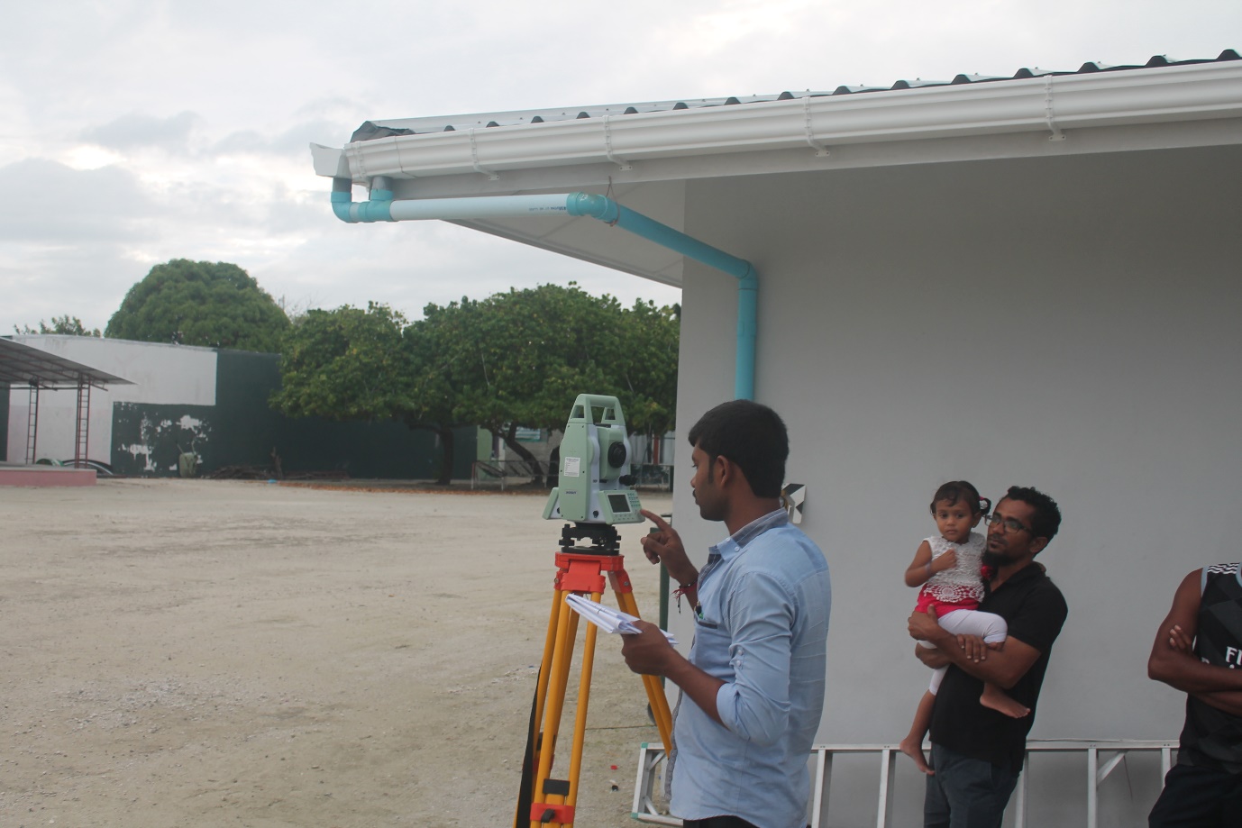
Detailed topographical survey of natural and man-made features was conducted using DGPS, Total Station and Digital Level instruments with data-recording devices and feature codes.
- Road-centre elevations and DGPS positions at approximately 20 m intervals, junctions and bends
- Cross-section points at carriageway and right-of-way limits
- Existing drain survey along road-survey lines and additional required points
- Obstructions, roadside encroachments, trees, light posts and electric posts
- Culverts, bridges and other hydraulic structures
- Underground utilities within 15 m on either side of the road centre line
- Waterlogging areas identified through local enquiry
Data processing and quality control
Field data was downloaded regularly and processed using TBC, Sokkia Prolink, Topcon and surveying software. Linear features were connected using feature codes and field-point sequences. Draft survey plans were physically verified on the ground by the senior surveyor before final processing.
Quality-assurance measures were followed throughout the survey. Day-to-day activities, accuracy, adjustment procedures and final survey sheets were checked by the senior surveyor.
Equipment and software
- Survey equipment
- Digital Level, DGPS and Total Station
- DGPS processing
- TBC software
- Data conversion
- Prolink
- Drafting
- AutoCAD
Working group
Team LeaderRanjan Kumar Mallick
Senior SurveyorTrailokya Das
SurveyorManas Rout
Surveyor EngineerSibaram Biswal
Assistant SurveyorBraja Kisore Das
CAD EngineerSS Das
CAD EngineerReshma Rosni Mishra